visit website photoshopqu.com
Often, the best way to be sure of your depth and angles is to render objects using Illustrators 3D tools. This tutorial will take you through building a 3D spark plug from multiple components and then expanding the image into a 2D vector diagram. Previous experience with Illustrators Revolve and Extrude tools will be necessary for this.
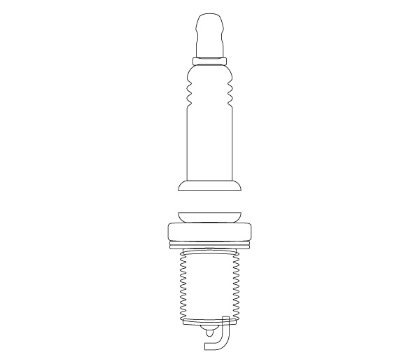
Final Image Preview
Below is the final image we will be working towards. Want access to the full Vector Source files and downloadable copies of every tutorial, including this one? Join VECTORTUTS PLUS for just 9/month.

Step 1: Bright Spark
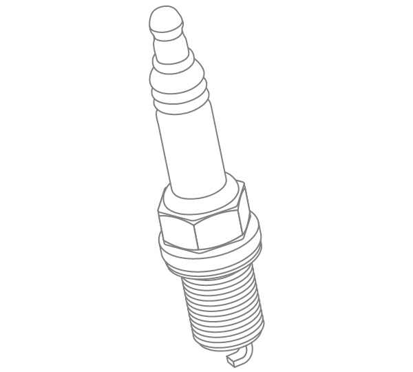
To begin with we need to know what a spark plug looks like. Grab one from the internet somewhere, alternatively here's an example to download if you feel more comfortable working from a quality image.

Step 2: Approach
We can see from the image that creating a single 3D object isn't going to be possible in Illustrator. The top and bottom sections can be 3D revolved, but the middle will have to be rendered using 3D extrusion. The bottom electrode will also have to be extruded.
For more information on these two techniques why not refer to VECTORTUTS tutorials Working with 3D Objects and Transparencies to Make a Vector Cola Bottle Design and Create a Can of Beans by Mapping Vectors to a 3D Object.
Step 3: Outline
For our two elements which will be revolved we can make one outline. The resultant gap in the middle will ultimately be filled by our extruded object and by revolving the two main sections as one, after we're sure of good alignment. Use the Pathfinder tools to build a silhouette of your plug.
Add the shapes all together (except the ground electrode at the bottom) using the Pathfinder tool and slice the result down the middle to create an object for revolving. Fill it with a fairly pale color so as to be able to clearly see the shaded and lit areas once revolved.

Step 4: Hexagon
The spark plug casing has six sides so we can easily construct it using an extruded hexagon. First we need to establish the dimensions of our polygon. The depth of the gap can be measured with the Measure tool and determines by how much we will have to extrude the hexagon.
First, go to Illustrator > Preferences > Units & Display Performance. You'll need to set General Units to Points, as Points will be used during the 3D rendering process. In this case you can see that having dragged the Measure tool across the gap, the Info palette is showing a distance D of 15pt. Feel free to change your units preferences back now, we just needed points for that measurement (although to be fair, the difference between px and pt is negligible).
The width can also be accurately measured, or judged by eye (and changed even when rendered in 3D if need be).

Step 5: Polygon Tool
Now we have our measurements (36px wide x 15pt high) we can set about building our hexagon. Select the Polygon tool and click once on the artboard. In the Polygon dialogue enter 18px for the Radius (any line segment from the center to the perimeter - remember that from school?) and 6 for the Sides. Click OK.

Step 6: Round the Corners
Select your hexagon and go to Effect > Stylize > Round Corners. Enter a value of 1px and click OK. Expand the resultant effect (Object > Expand) and the final hexagon ready for extrusion should look like the image below.

Step 7: 3D Revolve
Select your main object and go to Effect > 3D > Revolve... The 3D Revolve Options will hopefully be familiar to you. My object has been drawn so that I need to revolve it around the right edge, that's what I therefore select in the Revolve from drop-down. Check Preview and drag the positioning cube around until your object is rotated to the position you want. Also, note that we're not worrying about any perspective; that would really complicate things when we start combining objects together.

Take note of the values you've entered for the 3 axes of rotation, as you'll need these again: -30°, -14°, and 19°.

Step 8: 3D Extrude & Bevel
OK, we've made a good start, now let's continue with the hexagon we made earlier. We need it in 3D, at the correct angle of rotation and with the correct extrusion depth. We have all our information, so let's get on with it...
Select the hexagon and go to Effect > 3D > Extrude & Bevel... Now enter the values we already know for the angles of rotation: -30°, -14°, and 19°. Also, use an Extrude Depth of 15pt.

With Preview checked we can see that our hexagon is almost correct, the positioning cube is exactly the same as it was with our main object in any case...

However, because of the way in which Illustrator has assigned the faces of the objects, our hexagon is tipped exactly 90° onto its side. We need to add 90° to the value on the red axis (so it reads 60°) in order to bring our hexagon in line with the main body of the spark plug. Bingo!

Step 9: Major Tom to Ground Control
Our final piece of three-dimensionalism (is that a word?) is the ground electrode; that little piece which curves around the bottom to help make a spark. We have its 2D outline from earlier, now it's a case of 3D extruding it at the same angle as the other objects and to a suitable depth. Once again: -30°, -14°, and 19°. Next, put our ground electrode at the correct degree of rotation, then extrude it to 7pt, and it fits perfectly with our other objects.

Step 10: Breaking Up Is Hard To Do
We can arrange our objects together now, though because Illustrator doesn't cater for combining 3D objects our hexagon has to sit on top. Let's break them all up so we can layer them correctly. Select the objects and go to Object > Expand Appearance. Make sure you first have a copy of all these objects in case you need to refer to their original forms later on. Below you can see the resultant vectors - pretty complex objects!

Step 11: Group Therapy
These complex objects are built from groups. And groups of groups. And groups of groups of groups. Select the main body of the spark plug and ungroup it (Command + Shift + G). Now try and select just a portion of it. It could be that you need to ungroup again to start separating the components. Eventually you should be able to isolate the top section group from the bottom section group and therefore position the components in the correct layer order as shown below.

Step 12: Outlining The Issue
Now let's begin creating the segments of our diagram which will be outlined. You may find it easiest to place each one of the pieces we've already made on their own layers. Locking layers you're not working with will prevent difficulty in selecting what you're after.
Select the top section first and ungroup it (Command + Shift + G). Then select a smaller portion such as the one illustrated below. You need to be able to combine it's smaller parts to create one large object and this is done of course with the Pathfinder tools. In order to use the Add To Shape tool within the palette you need to ensure that the smaller parts are all separated. If ungrouping them doesn't work, try dividing them first using Pathfinder's Divide tool.
Once you've combined the smaller parts, expand them.

Step 13: Repeat Yourself
Having done it once you'll now have to embark on repeating the process quite a few times. Bear in mind that not everything needs to be included; your expanded 3D object will include many layers and faces which you can simply ignore. Build the pieces you need, fill them all with the same color and in the next step we'll work at cleaning them up.

Note: In retrospect, pink may not have been the best choice here...sorry.
Step 14: Sorting The Wheat From The Chaff
Select one of your newly made segments and go to Select > Same > Fill Color... to also select the others. Press Command + 3 to hide them, leaving just the excess from your expanded 3D object. There's quite a lot - and this can all be deleted. So do it!

Step 15: Simplify
With the rubbish out of the way, let's go about simplifying our remaining paths. Expanding the 3D object has created thousands of anchor points which will increase processing time and reduce the smoothness of your vectors. Press Command + Alt + 3 to reveal the objects you previously hid. Then, with them selected go to Object > Path > Simplify...
The Simplify dialogue will appear. Check Preview and see what effect your settings have on the selected paths. I suggest you keep Curve Precision at 100% so your objects remain true to their original form. Altering the Angle Threshold will change the limits to which your anchors can be angled. This again affects the shape of your objects and you'll notice that the higher the threshold, the more anchor points are needed and the more accurate your objects will remain. Find your own balance. In my case I've reduced the number of anchor points from 3196 to just 315. A massive improvement.

Step 16: Waifs and Strays
Switch to Outline view (Command + Y to toggle view) to allow rapid working (in any case, that pink color was offensive). With the Direct Selection tool, select and delete all the superfluous paths leaving only what is needed for the overall shape. Feel free to smarten up the paths however you see fit.

Step 17: Step Back and Admire
With a suitable fill color (white) and a nicely-weighted stroke you should start to get something like the image below. The hexagon has also turned out well, though we need to add some detail to it to highlight the sides.

Create a rectangle and go to Effect > Warp > Bulge. Enter 15% as a Horizontal Bend, click OK and then expand the resultant object.

Position the object on your diagram and use the Free Transform tool to place it into position. Holding Command while dragging the Boundary Box will skew as needed. Repeat for all three visible sides.

Step 18: Congratulations, It's a Spark Plug!
It will take a while, but eventually you'll be left with all your objects, cleaned and positioned correctly, together making a recognizable spark plug.
Step 19: Finishing Touches
Copy and Paste the whole thing (Command + C, Command + F) then use the Pathfinder tools to combine it all. Give this new object a thicker stroke, remove the fill and align the stroke to the outside. Adding a background with a suitable color will also give the diagram some atmosphere.
 Step 20: Further Finishing Touches
Adding a logo to the spark plug is also possible by mapping a symbol to your original 3D object. Again, refer to one of the previous VECTORTUTS tutorials to see exactly how this is done. By mapping a vector object to your spark plug, that too can be expanded as shown below.

Conclusion
With some labels pointing out what's what in the anatomy of a spark plug we have ourselves a technical diagram! Thanks to Illustrators 3D tools we've been able to build with near-perfect depth and angles, all aligned properly, finishing in a clear and simple style. Of course, 3D tools can be used to build a basis for all manner of things - go and experiment!
Subscribe to the VECTORTUTS RSS Feed to stay up to date with the latest vector tutorials and articles.